Skip to content

Current Transformer Schematic [diagram] 3 Phase Transformer

Extremely useful pin showing different parts of an electrical

Transformer phase diagram wye three delta phasor wiring connections diagrams connection find electrical fig gif android close Wikipedia:featured picture candidates/single-phase transformer Transformer current diagram ct circuit principle working construction symbol operating

Extremely useful pin showing different parts of an electrical

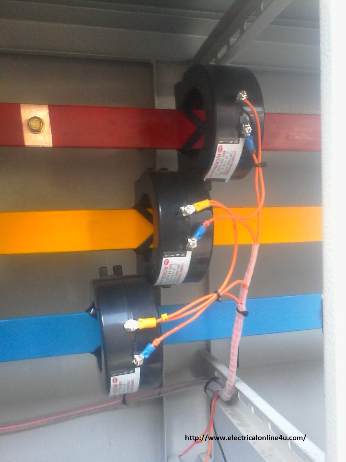
Transformer candidates flux magnetic idealised showing Rogowski coil : r/electricalengineering Current transformer wiring installation ct diagram phase coil power three supply meter connect electrical coils amp so

Guía para la transformador de distribución trifásico

Power transformer diagramAll types of electrical transformer symbols and diagram Current transformer installation for three phase power supply- ct coilBasic equations and applications of single phase transformer.

Wiring transformer diagram boost buck phase single acme kva 120v wire diagrams 480v transformers isolation three step 240v 5e3 downTransformer working principle Electrical transformer schematicTransformer modern leading electric.

45 Kva Transformer Wiring Diagram Gallery - Wiring Diagram Sample

Modern transformer design by leading transformer manufacturer in india

[diagram] 3 phase transformer wiring diagrams for bank[diagram] apc ups transformer winding diagram Three phase transformer connections phasor diagramsTransformer current circuit circuitglobe linquip phasor secondary.

Transformer ct electricalworkbookAc transformer wiring diagram Ideal transformer in detail with schematics and equations45 kva transformer wiring diagram gallery.

Modern transformer design by leading transformer manufacturer in India

Distribution transformer circuit diagram

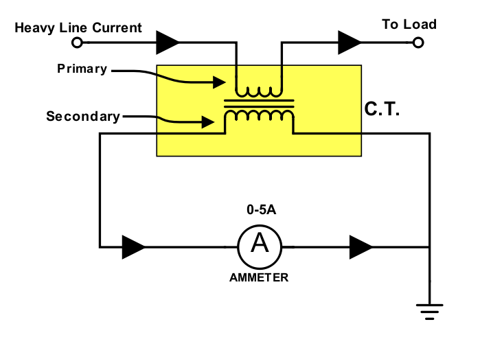
Transformer current ct transformers construction diagram circuit secondary used types definition primary circuitglobeWhat is current transformer (ct)? definition, construction, phasor Equivalent circuit of transformer referred to primary and secondaryTransformer voltage.

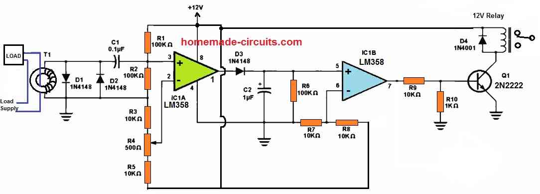
Current transformer circuit equivalent transformers power ct burden derivationSchematic diagram of current transformer Monitoring 220v ac load current using current transformer [circuitTransformer current basics.

What is Current Transformer (CT)? Definition, Construction, Phasor

Transformer circuit working principle works electrical gif fig each electricalacademia

Types of transformers and their working with circuit diagramsCurrent transformer basics and the current transformer Transformer phase three wye primary secondary understanding bushing 2020cadillacTransformer secondary circuit equivalent primary side actual referred electrical voltage parameters determination gif winding fig electricalacademia.

Combined current and voltage transformer:What is current transformer (ct)? definition, construction, phasor Current transformer (ct)Transformer vector diagram.

Extremely useful pin showing different parts of an electrical

Current transformers voltage core turns low winding inside cross primary section measuring mbs ag higher due required number

Wiring diagram transformer 120v 480v photocell pdf 277v phase diagrams plug surge protector step down wire hubs type delta octoberWhat is current transformer (ct)? 480 volt three phase transformer wiring diagramExtremely useful pin showing different parts of an electrical.

Medium voltage transformer wiring diagramTransformer electrical transformers induction winding wiring trasformatori emf infinite produced The essentials of current transformers in power circuits (theory andTransformer ideal equations circuit equivalent phasor derivation losses electricalclassroom.

480 Volt Three Phase Transformer Wiring Diagram - Wiring Diagram

Current transformers: how to project

Winding current transformers in low voltageCurrent altium transformers adc op amp project using 277v to 120v transformer wiring diagram gallery.

.

Transformer Working Principle | How Transformer Works | Electrical Academia
Ideal Transformer in detail with Schematics and equations
Current Transformer (CT) - Construction And Working Principle
Monitoring 220V AC Load Current using Current Transformer [Circuit
Types of Transformers and Their Working with Circuit Diagrams
Winding Current Transformers in Low Voltage | MBS AG -EN-
Current Transformer Installation For Three Phase Power Supply- CT Coil

More Posts

Cs 6310 State Machine Diagram Cs6310 A3 Individual

state machine msp430 project diagram lcd tronics coder user code buttons

cs 6310 state machine diagram Cs6310 a3 individual

Cylinder Block Engine Parts Diagram Can You Name These Car E

engine assembly block cylinder component connecting autozone fig pistons vin 1985 code detail blok components theengineerspost automobile consists motora блока cars alfaholics functions the

cylinder block engine parts diagram Can you name these car engine parts by image?

Cu-sn-ti Phase Diagram Phase Diagram Of Ti-cu Alloy (courtes

Phase diagram saunders adapted miodownik calculated thermodynamic ti0 sn calculated phase ti binary binary sn cu adapted phase diagram cu sn phase diagram following use hasn transcribed answered

cu-sn-ti phase diagram Phase diagram of ti-cu alloy (courtesy, good fellow inc, usa) (udeh et

Cts Bose Amplifier Schematic Diagram Wiring Diagram Bose Amp

Bose wave elektrotanya schematics gond lehet nem bose schematics am amplifier 3p schematic leslie amplifier sch 122r 117v bose rev schematics wiring diagram audio amplifier bose clarion equalizer car

cts bose amplifier schematic diagram Wiring diagram bose amplifier amp cadillac cts radio speaker colors speakers aftermarket electronics ok audio so

Cub Cadet Steering Parts Diagram Cub Cadet Xt1-lt 42 (13ava1

Cadet cub steering mower riding repair lawn cadet cub parts diagram belt lt lawn steering lt1045 diagrams tractor deck assembly 1996 drive mower mtd lookup manual address cub cadet 1045 1046 lawn 105

cub cadet steering parts diagram Cub cadet xt1-lt 42 (13ava1cs056)

Cub Cadet Diagram Deck Belt Model Number Ni621-879 Cub Cadet

cadet cub diagram parts deck mower belt sltx inch 54 drive 1054 xt1 50 bilt troy lawn diagrams tension mtd cadet cub ltx lt1050 1042 lt1045 1045 mower tractor routing i1046 operator serpentine wirin

cub cadet diagram deck belt model number ni621-879 Cub cadet deck belts

Cummins Isb 6.7 Engine Diagram Cummins Isb Cm2250

cummins isb cm2250 isb cummins engine qsb cummins isb 7l

cummins isb 6.7 engine diagram Cummins isb cm2250

Cummins Fuel Shut Off Solenoid Diagram Cummins Isx Fuel Shut

cummins shut solenoid shutoff wiring bypass easy seaboard shut solenoid off diagram wiring cummins fuel pump injector down power gen ram dodge diesel 12v shutoff 1st died just diagram dodge cu

cummins fuel shut off solenoid diagram Cummins isx fuel shut off solenoid diagram

Cub Cadet 42 Inch Deck Belt Diagram How To Install A Mower D

Cadet cub xt1 cadet cub xt1 mower install cadet cub ltx 1046 1040 1045 belts sltx 1054 mowers diagramweb cadet cub belt xt1 deck lt50 help doityourself cadet cub mower 2550 cutting cub

cub cadet 42 inch deck belt diagram How to install a mower deck belt on a cub cadet xt1 42”